 1
1
 2
2
 3
3
 4
4
ENGINE
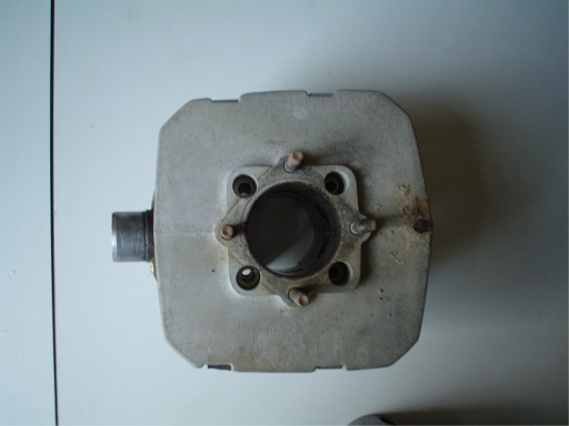
Cylinder
and piston
The SST cylinder has bore and stroke mm 56x50. Check the
ovalization and the presence of grooves on the inside walls. The cylinder is
chromed, bore isn't grindable. It can be buffed by a qualified
mechanical workshop. There are five piston sizes with diameters ranging from 5595
to 5599 hundredths of a millimeter. The cylinder-piston tolerance is +/-5
hundredths of a millimeter. It is appropriate to combine the cylinder with its
respective piston. The piston has one towards mounting which is indicated
by the arrow printed on top and the same must be facing forward.
Spark
plug and air filter
Replace air filter and spark plug: during the
exercise must be replaced every 3000 and every 5000 km. Screw the spark plug not
too enough to avoid breakage of head threads. For correct spark plug type see following references: Champion N3, Magneti Marelli CW7LP; NGK B8ES; BOSCH W3CC.
Check that the cover (pipette) not be oxidised inside. Unscrew the contact
within the pipette and remove the power cord. Cut the piece of
oxidized cable or replace it if necessary. Air filter type is "tall type"
for models built until 1983.
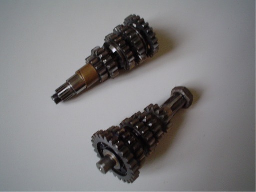
Bearings and oil seals
In case of engine opening you should replace all bench bearings, bushings and oil seals. Before disassembling engine you may should check the bearings worn. Shake the axis on which is mounted the pinion, or shake the axis on which clutch is mounted: in both cases there should be no play on the axis. A spill of oil engine from countershaft, pinion side, is index of broken or heavily worn bearings. This situation can lead a gear box block, because misalignment of primary and secondary shafts. Clean the inside of the engine block by oil sludge and impurity deposited at the bottom. The engine can be assembled using a special motor sealant for formation of the seals. Bearing sizes are follows: bench left 6204/C3; bench right 6204/C4; bench right outer 6203/C3. Size of oil seals are follows: bench left 20x35x7/7.5; bench right 17x40x7/7.7; countershaft: 25x37x5.
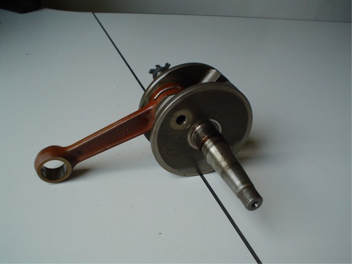
Crankshaft and connecting rod
One of the possible faults is caused by the fault of the needle bearing located at the foot of connecting rod (more rarely at the head). A loud rattling noise can be felt by running engine. To separate the crankshaft from the connecting rod you will need to use an hydraulic press. Connecting rod, pins and in some case, the piston, must be replaced.
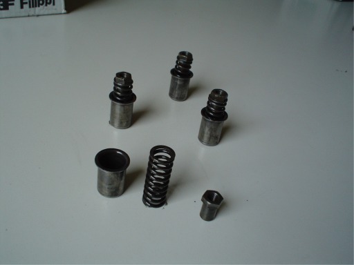
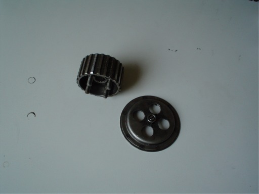
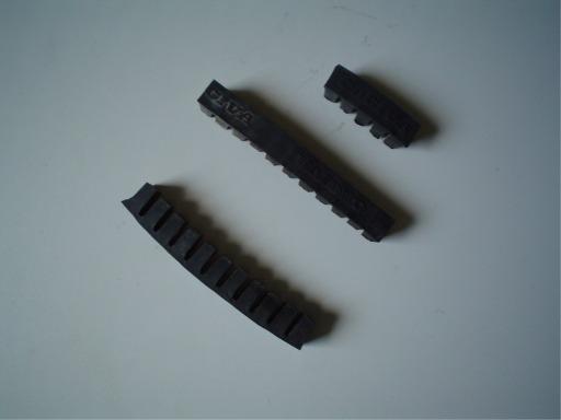
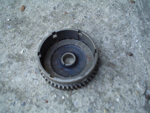
Pictures: (1) cylinder, piston, pin, (2) cylinder, (3) crankshaft with connecting rod, (4) primary and secondary shafts, (5) elements of the gear, (6) clutch springs and cups, (7) hub and clutch cover, (8) clutch disks, (9) oil pumps: long type and short type, (10) anti-vibration rubber, (11) clutch bell, (12) carters.
1
2
3
4
 5
5
 6
6
 7
7
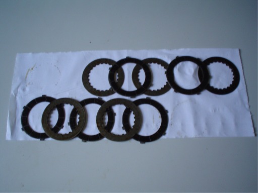 8
8
 9
9
 10
10
 11
11
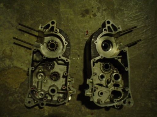 12
12
CARBURETOR
DELL'ORTO VHBT 27 AD (ex VHB 27)
The carburetor should be cleaned
and adjusted. General inspection: bring the bike on the center stand. Start the
engine and warm it up, after having done it idle for a few seconds, open the
throttle suddenly. The engine must respond immediately. If the engine is turned
off or choking is necessary to clean the carburetor, inside and out, and replace
all gaskets, sprinklers, and needle valve (the latter are subject to wear). In
particular: needle V16, summer jet 82, jet skiing 85 (NB: 90 jet models with
electronic ignition motoplat), idle jet 50 of the series (in the case of low
resistance can be mounted above a jet, not later than 60). To adjust the minimum
turn the screw top (large) to increase the speed screw, unscrew to decrease. The
air-fuel mixture is controlled by the lower screw (small): tighten the screw all
the way, loosely. Then unscrew making them take a lap and three quarters.
Carburation
An important control is about carburation that you make when looking at the color of the electrodes of the spark.
If the color is light brown electrodes (hazelnut) carburation is OK.
If the color is white, the mixture is too poor (too much air, overheating, galling).
If the color is black, the mixture is too rich (too much gasoline, electrode plumb, risk of stop and no restart).
LUBRIFICATION
If possible, use synthetic 2T oil like Castrol TTS or MOTUL 710. The bike has no oil gauge so you should periodically check the level through the transparent plastic tank, located under the fuel tank. The autonomy of one kg of oil is 700/800 km. Lubrication is left to a pump type Mikuni. With the engine idling, check that the point marked on the butterfly coincides with the mark stamped on it. If so, turn the adjusting screw.
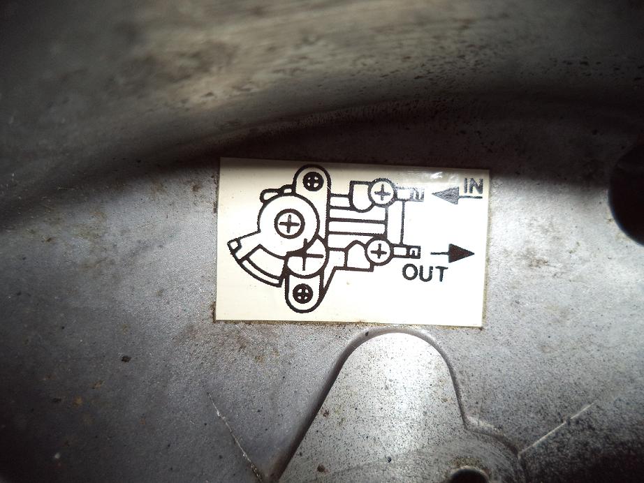
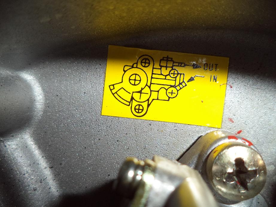
NOTE: the older models are fitted with a "long type" pump (for example, HD-Cagiva models), while the newer models are fitted with a "short type" pump (9). The two pumps are not interchangeable because the casings that house them have the screw holes in different position. If you really want to trade exchange also need housing.
WARNING! Pumps "long" and "short" have the inlet/outlet lines inverted. The "long type" pump (13) is fed into the nozzle at the top and emits oil at lower nozzle. The "short type" pump (14) is fed into the lower nozzle and emits oil at the higher nozzle.
 13
13
 14
14
ELECTRICAL
CIRCUIT
Battery
If the battery is old it must be replaced (12 Volt 5/7Ah), the electrolyte level should be checked once a month. Do not reverse the battery poles. Do not start the bike with the battery disconnected from electrical circuit! Always remove the battery during long stops, such as during winter months.
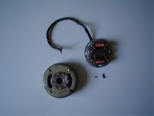
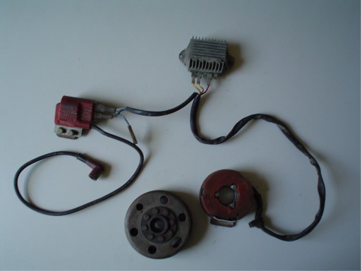
Flywheel
Until V.I.N. 6F-108815 the bike was equipped with a DANSI wiring system (contact breaker, then abandoned and replaced by electronic MOTOPLAT). The flywheels mounted on older models were poor of quality (in particular they were subject to breaking of the magnets). The most recent series of DANSI flywheels is the n. 102222. It can be removed using a puller tool with internal thread 30 mm, pitch 1.5 mm. MOTOPLAT flywheels can be removed using a puller tool with external thread 26 mm, pitch 1.5 mm.
Contact
breaker DANSI
Older models
were equipped with a DANSI electrical system, contact breaker type. Check the wear of the
contacts and replace them if necessary. Replace the condenser also. The capacitors
have a life cycle and are destined to end. The typical failure typically occurs
when engine is warm: more heat and the bike has more power problems, until to stop.
Usually the bike starts again only when engine is cold. To replace the capacitor will be necessary to
disconnect the electrical cables green and black and then weld them to the new
capacitor. The maximum aperture size of contacts is 0.40 mm. The
condenser has capacity of μF 0,29.
To recognize the "contact breaker" model, you may look at the dashboard where there are mounted three lights: red "gen", orange "turn", blue "high beam". If while driving the red light stays ON, it means that the controller is not charging the battery. In many cases this is due to blown fuses or at the fuse holder poles that eventually being oxidized. Replace them (16 amperes). If the light stays ON without flashing orange means that the flasher is broken. The bike is fitted with a Lucas flasher, but also works well with a compatible 21W flasher.
Electronic ignition MOTOPLAT
Later models were equipped whit electronic ignition system (do not confuse with "electric start!") provided by the spanish Motoplat. On the dashboard, lights are green "lights", orange "turn", blue "high beam". The SST 250/350 models are equipped with the same lights with the variant "neutral", green. MOTOPLAT version mount fuses 15 ampere and an "electronic ignition" label is attached on the left crankcase.
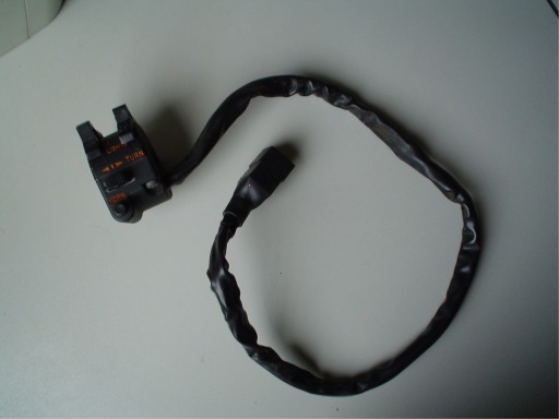
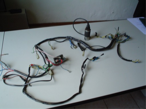
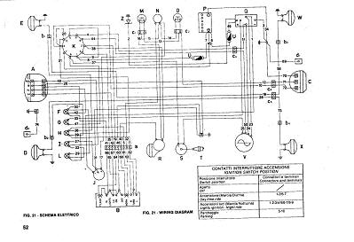
Pictures: (15) complete switch, (16) electrical system for contact breaker Dansi.
 15
15
 16
16
Below: (17) ZIP file containg wiring diagrams for electronic ignition Motoplat, contact breaker Dansi and Harley-Davidson.
 17
17
IGNITION
TIMING
Contact breaker engines DANSI (flywheel and
mechanical switch) (18-19)
a) Disconnect the spark plug and remove left crankcase side cover. Turn the rotor a small amount, untill contact breaker points are opened at the maximum amount (you should see the contacts through the control window). Insert a feeler gauge (mm 0,40) between the contacts and check there is no play in either way. In other words, the gauge must fit perfectly between contacts. In this case no adjustment is required.
If adjusteent is required, then loosen the screw that holds the fixed contact for a small amount. Insert a screwdriver into the control window and with it move in + or - the fixed contact until reaching the maximum aperture size of mm 0,40. Thighten the screw of fixed contact, turn rotor and check the gap again to be sure all is ok.
b) After adjusting the contacts must be checked the ignition timing. Remove the seat and attach to the coil poles a light bulb. Slowly turn the flywheel counterclockwise until the notch "A" engraved on it is close to the notch engraved on left crankcase. Now turn the flywheel slowly until the notches match perfectly. The bulb connected to the coil should light up at this moment. Neither before nor after.
If the bulb lights up before, the ignition time is to early; If the bulb lights up after, the ignition timing is delayed. Adjustment is necessary.
c) Adjustment instructions: dismount the flywheel and loosen the three small screws that lock the stator to the engine, that be enough to afford, forcing slightly, the rotation of the stator. Mount the flywheel does not lock it. Spin the flywheel counterclockwise and verify the ignition timing as above. If the bulb goes lights up before that the notch "A" doesn't match with the notch engraved on crankcase engine, (ignition too early), you will have to rotate the stator counterclockwise, giving him small shots with a screwdriver through the control window of flywheel. Conversely, if the bulb lights up after (ignition timing delayed) you will have to rotate the stator clockwise. Reached and controlled the exact point of ignition, carefully remove the flywheel without moving the stator. Tighten the three screws of stator, reassemble the flywheel and lock it.
 18
18
 19
19
Below: (20) ZIP file containing wiring scheme for stator Dansi 101511 and 102222.
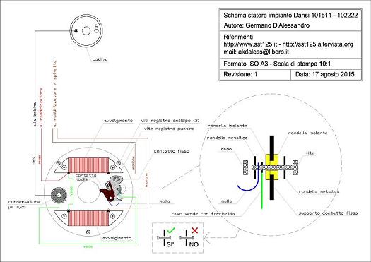 20
20
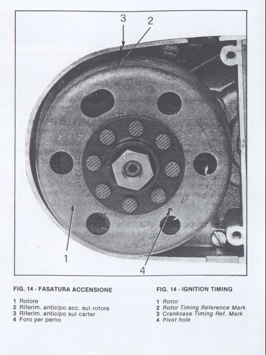
Electronic ignition engines MOTOPLAT (21-22)
For inspecting flywheel alternator remove left crankcase cover. To check the ignition timing proceed as follows.
a) Assemble the stator plat on engin without fully tighten it.
b) Assemble the rotor and insert a pivot (2 mm diameter) in the hole; turn the rotor until the pivot come in the stator plate hole.
c) Turn until the rotor mark is in line with the crankcase reference mark.
d) Remove the rotor, lock the statoric plate; then assemble and lock the rotor.
 21
21
 22
22
TRASMISSION
The transmission group (sprocket, pinion, chain) are subject to normal wear and tear of exercise. A worn chain, during the march, undergo deformations with variable speed that brought in contact with some parts of the chassis, creating a noisy burst effect. The phenomenon is felt particularly in fifth gear. The new chain must adhere to the sprocket, without any swing. A worn chain can derail while driving. Tighten the chain, without bringing it live, using the chain tensioner to the rear wheel nut. The free-swinging vertical chain should be about 2 cm. Periodically lubricate the group catena. The group pinion, sprocket and chain must be replaced every 10,000 km, whereas at 5,000 km a change must be made of single chain. The pinion has 14 teeth, while the sprocket has 62 teeth (both models: integral and spokes wheel). Up to the chassis number 6F-91938 the integral wheel was supplied with a sprocket of 59 teeth.
You can purchase the kit provided by PBR (only through authorized dealers).
Kit PBR for spoke wheels = EK205 (pinion 14 - sprocket 62)
Kit PBR for integral wheels = EK267 (pinion 14 - sprocket 62)
Below: (23) sprocket 62 teeth and pinion 14 teeth.
 23
23
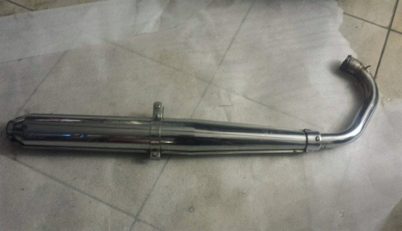
EXHAUST
Overview
The bike mount a
Lafranconi muffler serie
(DGM 30229S).
The muffler is plated with
connections to 3 springs
and support bracket.
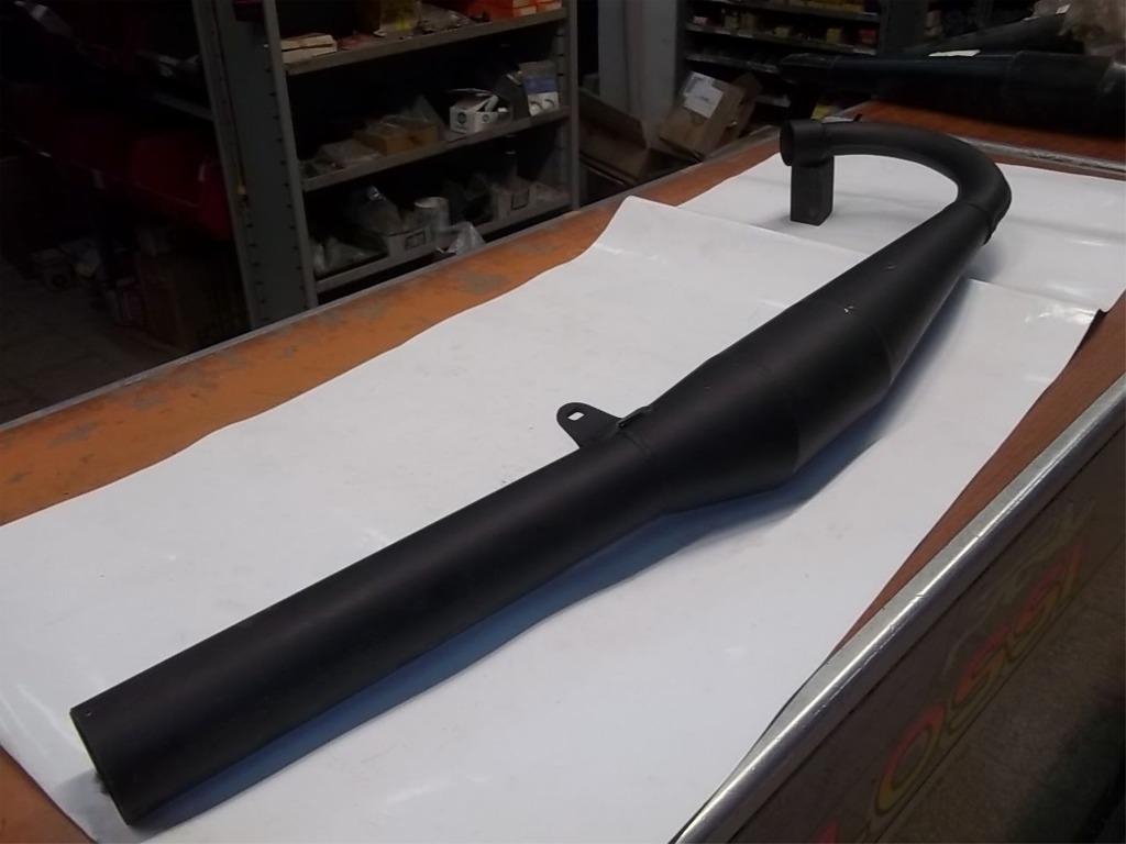
At the time, there were also other
expansion mufflers produced
by third parties (the
famous Giannelli, Figaroli,
Proma). The expansion
muffler requires the replacement of
maximum jet
(largest 5-7 points)
and a greater
ignition timing.
The expansion provide higher
performance than the original, even
if very quickly presents
the inconvenience of
silencer obstruction.
Pictures: (24) Lafranconi muffler sierie; (25) racing muffler Giannelli.
 24
24
 25
25
Disassembly
Lafranconi is a muffler type with diaphragms.
One
of the drawbacks of
this is that of the muffler
clogged. If running
the bike "stuttering"
and fails to pick up speed,
most likely the muffler is
clogged. The unburnt oils
form with time carbon
deposits which are deposited on
the conduits. Sometimes escape
from the muffler black solid
debris. Regular cleaning
prevents this phenomenon.
The muffler of Lafranconi
series has a removable
spak arrestor.
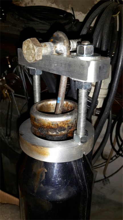
To repeat the process must
first obtain a rugged hook
and hook the exhaust pipe from
the inside. With the help of an
extractor it will be possible
to extract the spark
arrestor without
ruin the
terminal part of
the muffler.
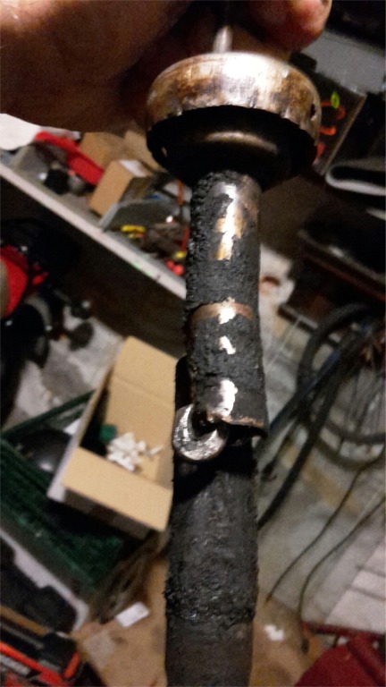
Pictures:
(26) Step of
spark arrestor removal;
(27) spark
arrestor pulled out, the image shows
the position of the hook.
 26
26
 27
27
Internal cleaning
Once
you extracted the spark arrestor
will be possible to proceed to the cleansing of the
muffler with use of sodium hydroxide (NaOH), commonly known as caustic
soda. Caustic soda is a strong base, hygroscopic and in contact with water
produces an exothermic reaction.
CAUTION:
caustic soda is a
dangerous
chemical
mixture; Avoid
any contact with eyes and skin because it
can bring
severe burns. Caustic soda should be handled with care, using appropriate protections: nitrile gloves, mask and goggles.
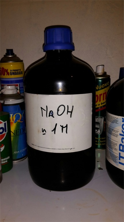
To
prepare the solution will
be necessary
about 50 grams of caustic soda every
1
liter of water (50
g / liter). This
proportion will produce a pH 14
solution. Pour the crystals of sodium
hydroxide in a flask
and pour hot water. Mix
the solution with an iron rod. The crystals begin to melt,
the chemical reaction produce a lot of heat.
The cleaning can be
performed using one of these two different systems:
a)
pouring caustic soda directly into the muffler. With this system, it will be necessary about 3 liters of solution.
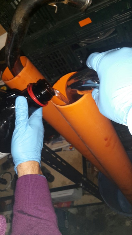
b)
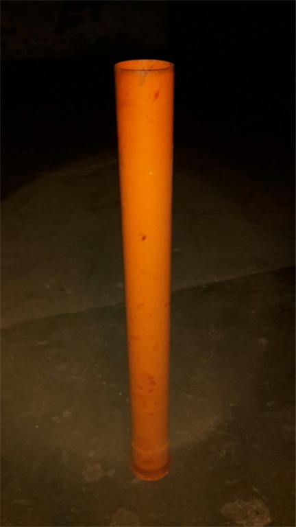
pouring the caustic soda inside a container, usually a PVC
tube placed
in vertical
position (height
cm 100,
diameter cm
10), which houses the muffler. The
tube will have a lower end cap, sealed with Teflon. With this system, it will be necessary about 6 liters of solution.
Leave
the solution from 2 hours to 24 hours. At
the end it will be necessary to empty the muffler from the solution and rinse
the inside with water. Will
come from the muffler debris and fouling. If necessary, repeat the operation several times.
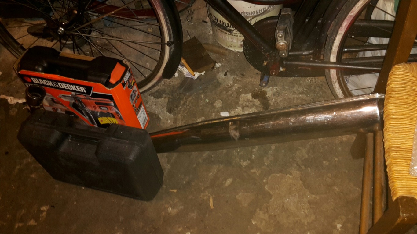
Pictures:
(28) flask containing
sodium hydroxide solution; (29-30) 1st
method with
filled muffler, correct
position of the muffler; (31-32)
2nd
method with vertical tube,
muffler
filling.
 28
28
 29
29
 30
30
 31
31
 32
32
INSTRUMENTS
Speedometer
The
rupture of the rope is a major cause of the failure of the speedometer. The rope
breaks generally to the wheel. More rarely may have broken the beveled gear
odometer that postponement must be periodically greased. It is recommended not
to tighten the screw ever strong national odometer because in future could prove
unable to unlock it.
Tachometer
The SST 125 tachometer is electronic, having free field from 0 to 7000 rpm, a threshold of attention (yellow) from 7,000 to 7,500 rpm and an area of overload (red) from 7,500 to 10,000 rpm. NOTE: the counter of the models with "power pins DANSI" and model with "electronic ignition MOTOPLAT", although the same outside and inside, are not compatible. The difference is that the calibration has been set by the factory at the time of production. To recognize with which model the tachometer is compatible is necessary to observe the plate attached on the back: the parameter 20000 is compatible with the DANSI model, the parameter 30000 is compatible with the MOTOPLAT model.
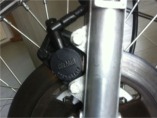
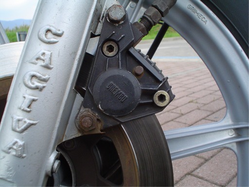
BRAKES
Check the wear of the pads and the state of the brake disk. The disc is 260 mm with 6 holes for the screws and a thickness of 4.5 mm. The central hole has a diameter of mm 80 for the model with integral wheels and a diameter of mm 60 for the model with spoke wheels. The brake caliper is a Brembo P28N-RH, with a mm 28 piston and spaced of the fork coupling by mm 88. Older models mounted a Brembo P04 universal caliper, with a mm 32 piston. Pad and piston are welded as one piece. To replace the brake fluid and do the complete cleaning, proceed as follows.
a) Slightly loosen the bleed valve on the caliper.
b) Attach a rubber tube on the end of the valve and make it end in a container of raccolta.
c) Spill the old liquid by repeatedly pressing on the brake lever, until the empty impianto.
d) Loosen the inlet pipe on the caliper with a 14 wrench.
e) Loosen the screws holding the caliper half. The screws are very hard and it's easy to damage them. The Kit Brembo contains new screws.
f) Finally remove the caliper from the fork and disassemble it by removing the bolts loosened in step "e".
g) Remove the cylinders on both sides of the caliper half. To do this blow compressed air in the ducts.
h) Clean communicating vessels of any debris. Use Kit Brembo package to change all rubber seals and grease the cylinders.
i) Fit the caliper with new screws taken from the kit.
j) Install the caliper on the fork by tightening the screws. Let loose only the purge valve with a tube connected as point "b".
k) Fill the system by pouring new oil into the bowl located at the righ side of handlebar, repeatedly pumping on brake lever.
l) When oil comes out of the tube previously connected, you must tighten the bleed valve to close the circuit.
m) Pour more oil into the bowl and act on the lever until the system enter into pressure.
Use only DOT 4 brake oil.
Below: (33) caliper Brembo P04, (34) caliper Brembo P28N, (35) pad mm 51,5 x 35,2 x 6,3 maximum, (36) disassembled caliper
 33
33
 34
34
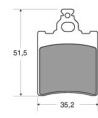 35
35 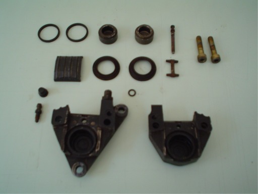 36
36
WHEELS
Always
change tires during the restoration. The old tires are subject to cracking and breaking along the
furrows. The old
tires tend to stiffen and
lose grip on the road.
Replace bearings too. The bearings are broken when there is clearance between
the wheel and the axis on which it is mounted.
The model with spokes have the following characteristics: front rim size 19 x 1.60 and rear rim size 18 x 1.85. The spokes are of three different types: those for the front wheel are of a single type and have a diameter of 3.5 mm, while those of the rear wheel are of two different types (internals and externals to the hub) and they have a diameter of 3 mm.